
| 1961 PV544 Project - Update 23 |
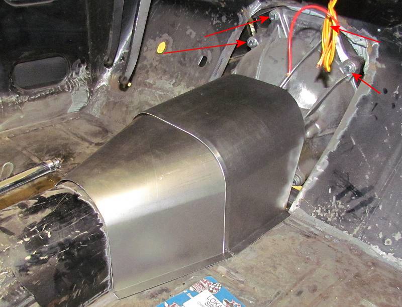
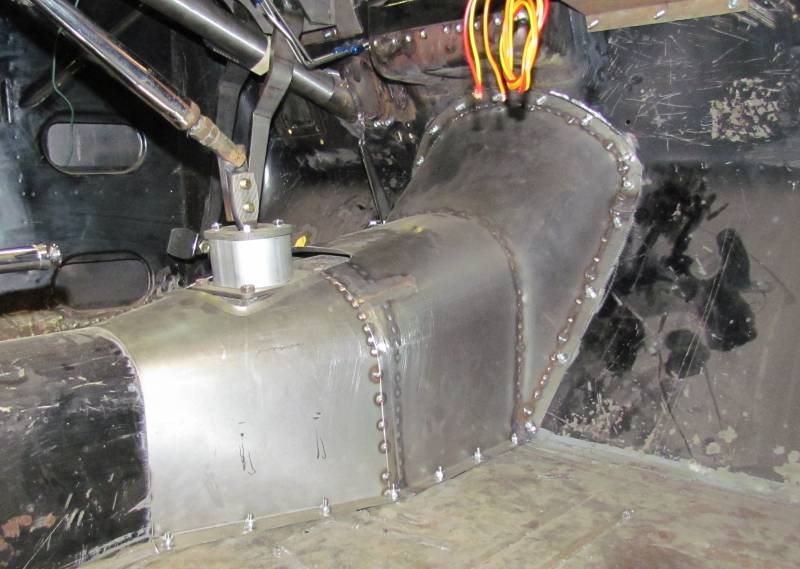
Transmission Tunnel / Fuse Panel Locate / Nerf Bars By Frank Colgoni Transmission Tunnel Below: When it became obvious that the top four bolts of the bellhousing (see red arrows) would not be accessible with a fixed transmission tunnel (that is, from above in the engine bay or from below), a removeable tunnel became a necessity. The first two pieces of the tunnel are loosely in place here. |
 |
Below: As seen from the engine side with the engine and transmission removed. |
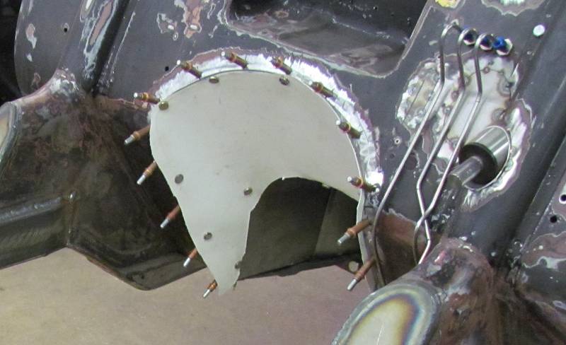
Below: Template in progress for the front section of the tunnel.
|
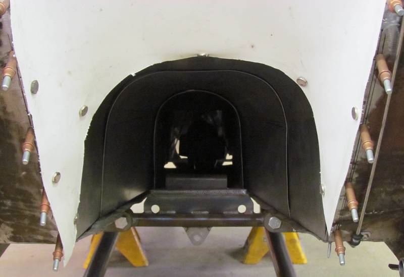
Below: Again, from the front.
|
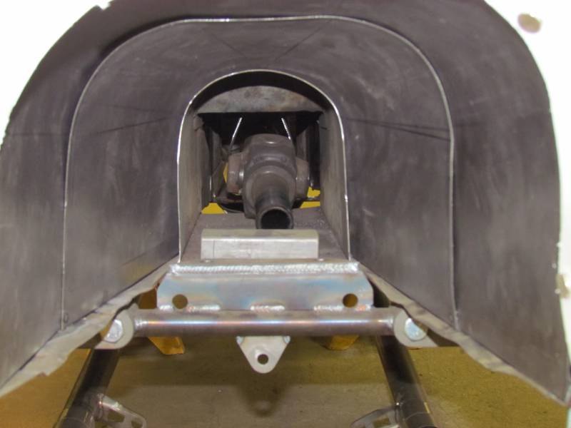
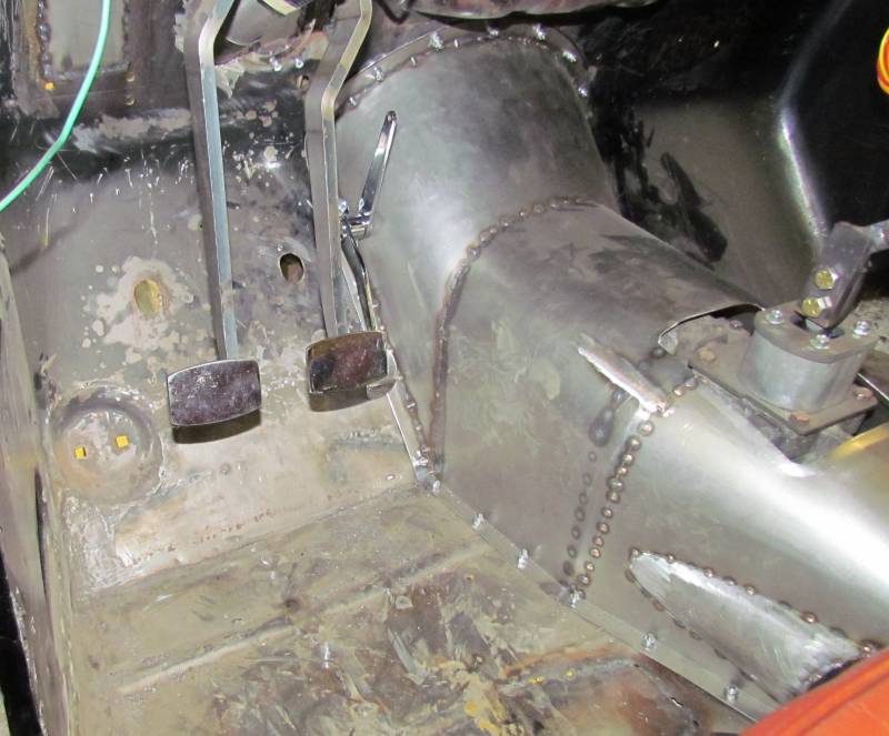
Below: Finished tunnel fastened in place. Machine screws will be replaced by nutserts.
|
Below: The other side showing a "bump" in the tunnel for the speedometer sender
|
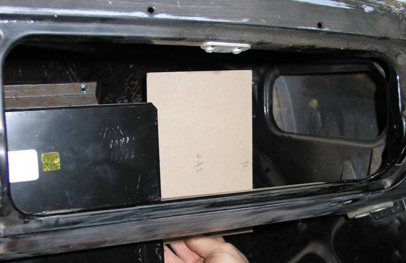
Fuse Panel Locate If you have had a look at Update 17, you'll know that we are using a Ron Francis Wiring Express panel and associated wiring. While we were waiting for our panel to arrive, we made up a template of the panel to see what made sense in terms of placement. Behind the glovebox door and to the right of the heater made sense in "portrait" orientation. To facilitate initial wiring and for future access or for adding additional electrical accessories, I wanted the panel to be drop-down.
|
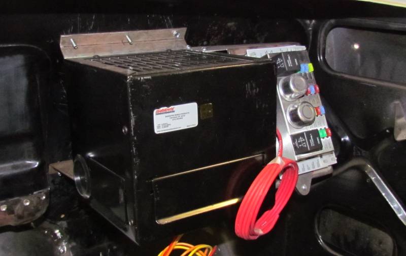
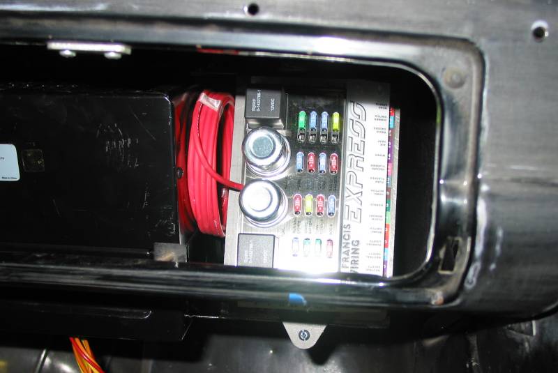
Below: Here you can see the Express panel mounted in its finished position.
|
Below: Viewed through the glovebox door. The panel mount shares the heater mount with the top edge of the panel located under a raised lip. The bottom edge of the panel is secured by a removeable clamp. By removing the screw, the clamp is released and the panel will drop down. Enough extra wire will be allocated to allow for that movement. Because wire termination occurs at the source and at the Ron Francis Express panel. This is easlily achieved. The only wire coming out of the panel is the battery feed. More on wiring in a future update.
|
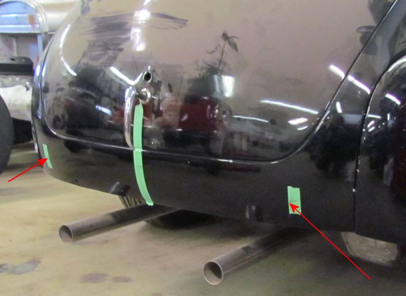
Nerf Bars Below: Originally, The PV544 Volvo had a traditional bumper with overrider bars at the ends. As I wasn't going to use the bumpers and, after much reflection, I decided on nerf bars. To begin the process, I identified the centerline of the car (license plate will go there) then picked a starting location for the nerf bars (red arrows).
|
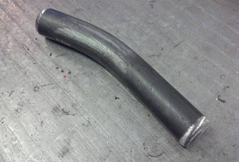
Below: Using a piece of flexible tubing cut to length, I bent it to the shape I felt best suited the rear pan placement. Using my tubing template, Grant at Schwartz Inc. created the nerf bar below.
|
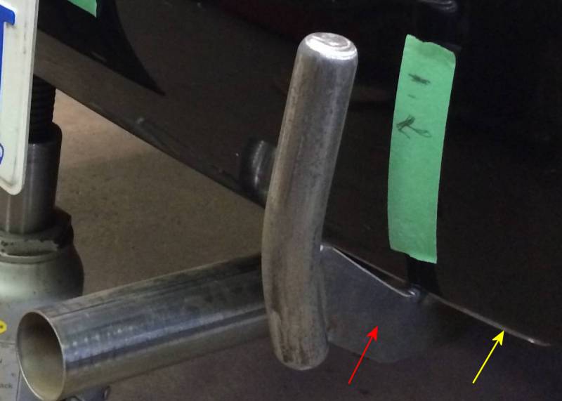
Below: With the nerf bar in hand, I moved on to create a template for the braket that would attach the bar to the car (red arrow). Because the pan would not be substantial enough to mount the bracket to, I created another template of the complete underside of the rear pan. That was translated into a 1/4" plate (yellow arrow) that was drilled to accept the nerf bar brackets and a license plate bracket.
|
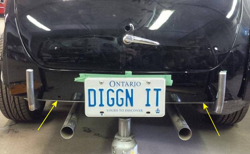
Below: The completed nerf bar and license plate setup. The yellow arrows point to the supporting structural plate. The license plate will be illuminated by LED bolts.
|
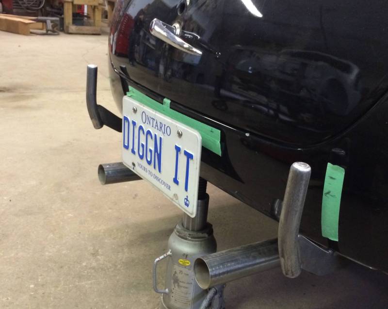
Below: Another view
|
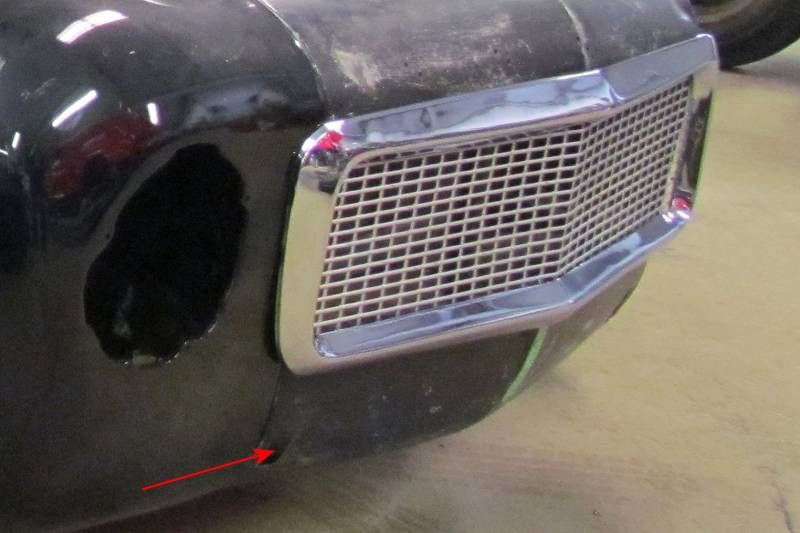
Below: Matching nerf bars will be fabricated for the front and the brackets will exit through the front pan where the original bumper brackets exited. More on that later.
|
Resources:
Schwartz Inc.
Next: T5 Transmission Reconditioning