| 1961 PV544 Project - Update 18 |
Completion of Steering Column / Pedals By Frank Colgoni In Update 15, I covered the rationale for the placement / repositioning of the new steering column. In this update, I'll provide some "after" photos and additional details. Also, details of pedals and associated plumbing will be covered. If you haven't seen Update 15 yet, have a look before proceeding with this update. |
Below: A photo from Update 15 showing the proposed new centre for the steering column placement.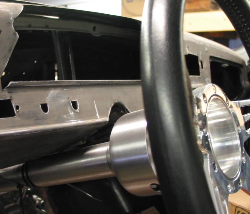 |
Below: A photo from Update 15 showing the new exit location for the bottom end of the steering column.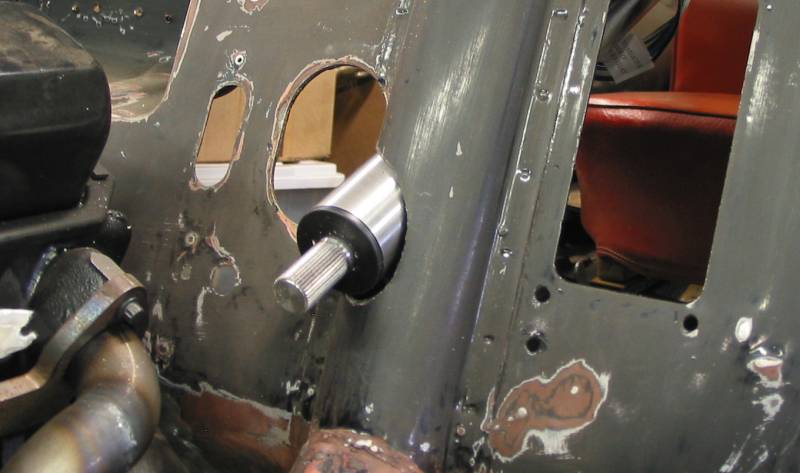 |
Below: The result of the steering column dash notch being cut out and moved left to correspond with the new centre line shown above. One dash knob hole was relocated to the right side of the column. 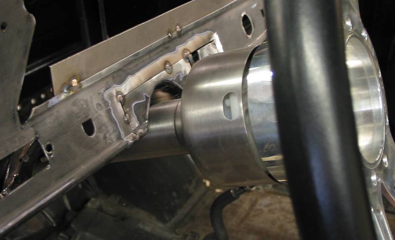 |
Below: An underside view. 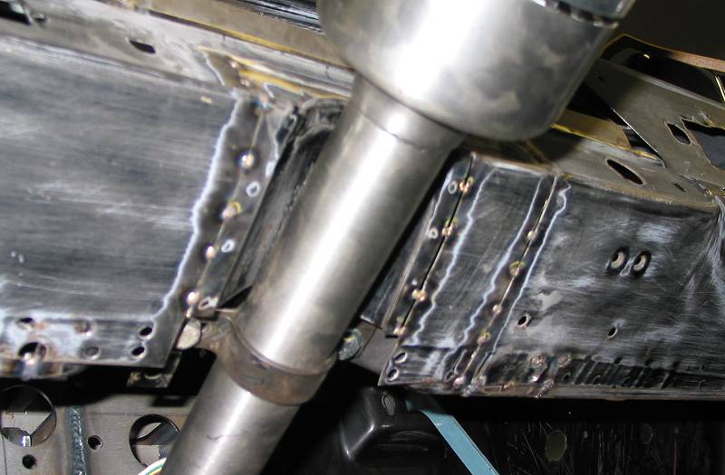 |
Below: The bottom end of the column is now supported / located by a tube sleeve. This also serves to stiffen the area in the firewall where the unibody frame rail upper channel was cut. (All work done by Schwartz Welding) 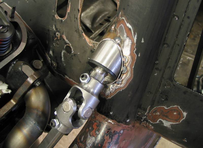 |
Below: Routing of the steering linkage down to the steering rack.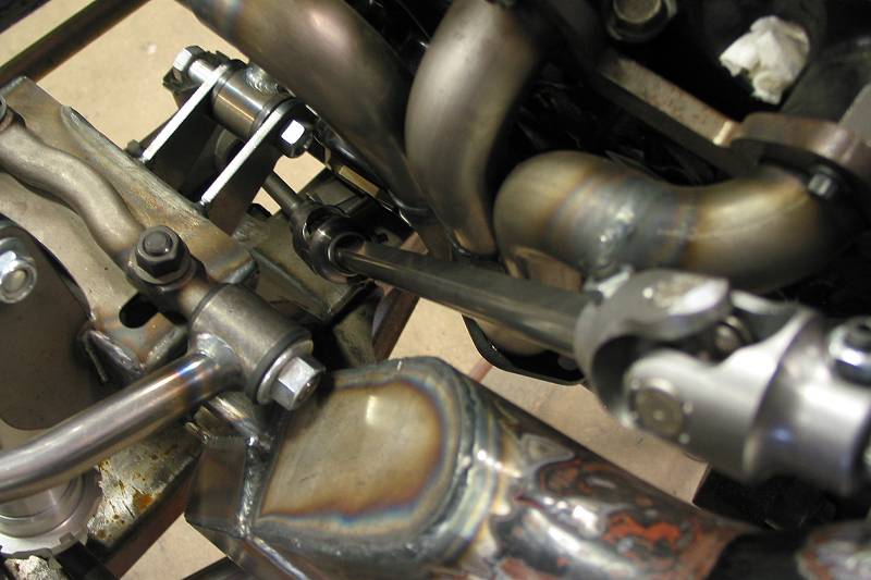 |
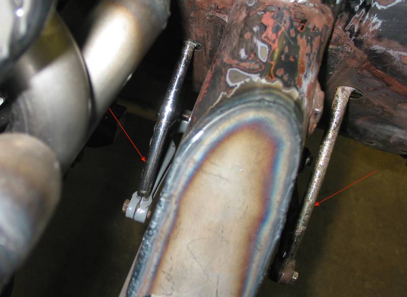
Below: This is the stock pedal setup in all Volvo PV544s. Both the clutch and brake pedals go through the toe board and arc down to arms that pivot off an underbody frame reinforcement channel. |
Below: The red arrows point to the stock pedal arms (brake on left and clutch on right) as seen from the top where they exit on the engine side of the toe board. They are clamped into the ends of the swivel arms. The brake arm actuated a master brake cylinder that was situated in front of the arm bolted to the unibody frame rail. It became obvious at this point that that area was going to be occupied by at least the header collector flange. A different pedal solution would need to be found. |
Below: A view of the stock clutch pedal location which was outside the frame rail and in the driver's side wheelwell. It made a mechanical connection through the underfloor frame rail support channel to the clutch arm at the bellhousing. 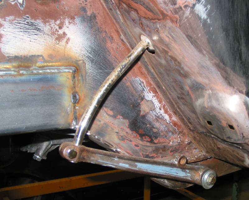 |
Below: The final pedal solution became a 180 deg. Kugel setup. Initial fitting shown below. At this point, the pedals are tacked to a mounting plate which is bolted to the firewall. 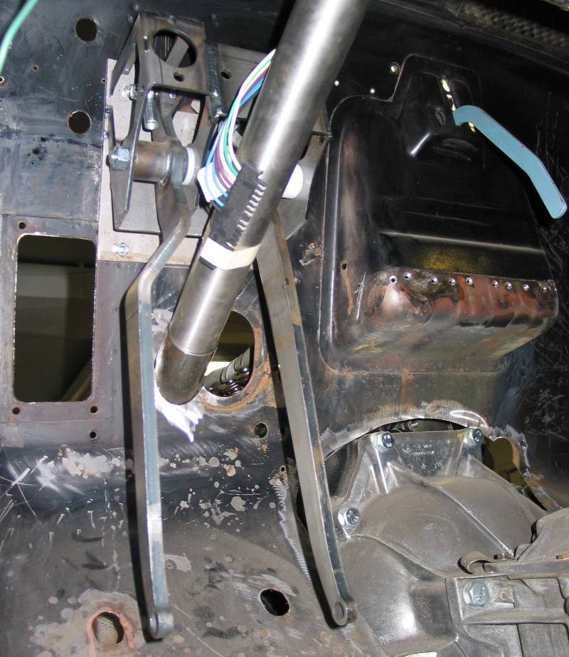 |
Below: Another view of the complete pedal setup. 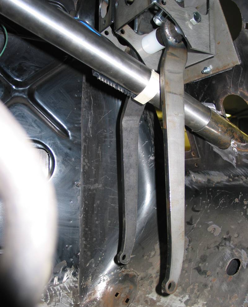 |
Below: Just the upper bracket showing where the brake and clutch master cylinders mount. 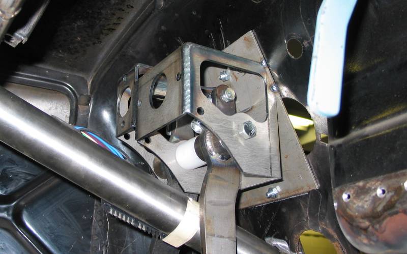 |
Below: Wilwood clutch master and MP Brakes brake master mounted. 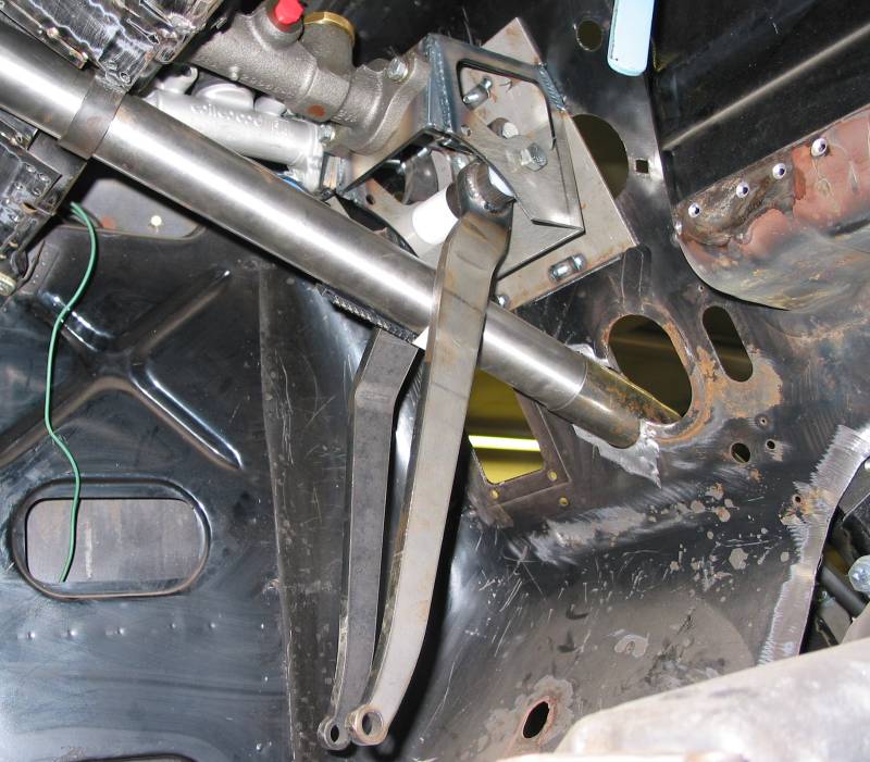 |
Below: Lines running to and through fireweall. 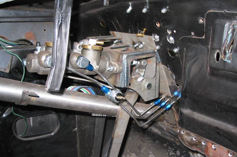 |
Below: Mounted remote reservoirs and lines exiting firewall. Thanks to Schwartz Welding.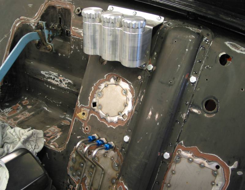 |
Below: Schwarzt line clamp / additional work on firewall and column support sleeve. 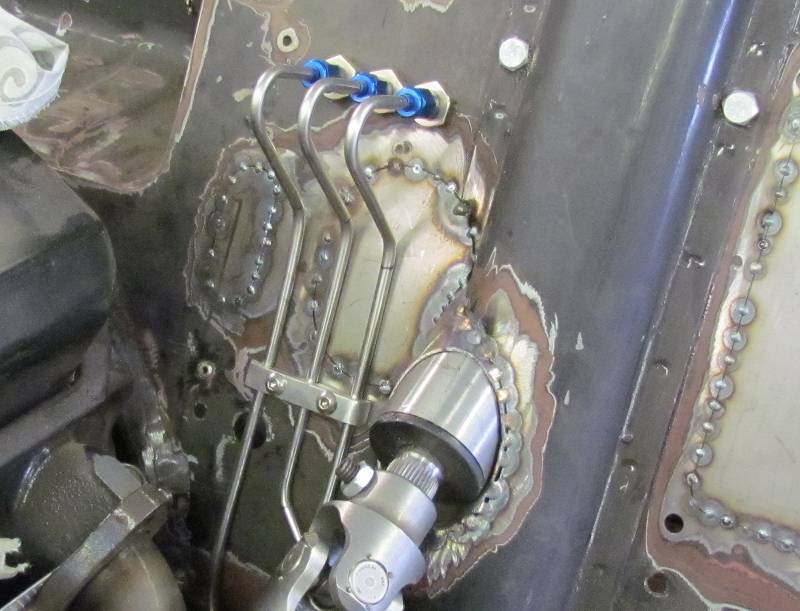 |
Resources Next: Shifter Considerations |